Layout Power Supply Amplifier
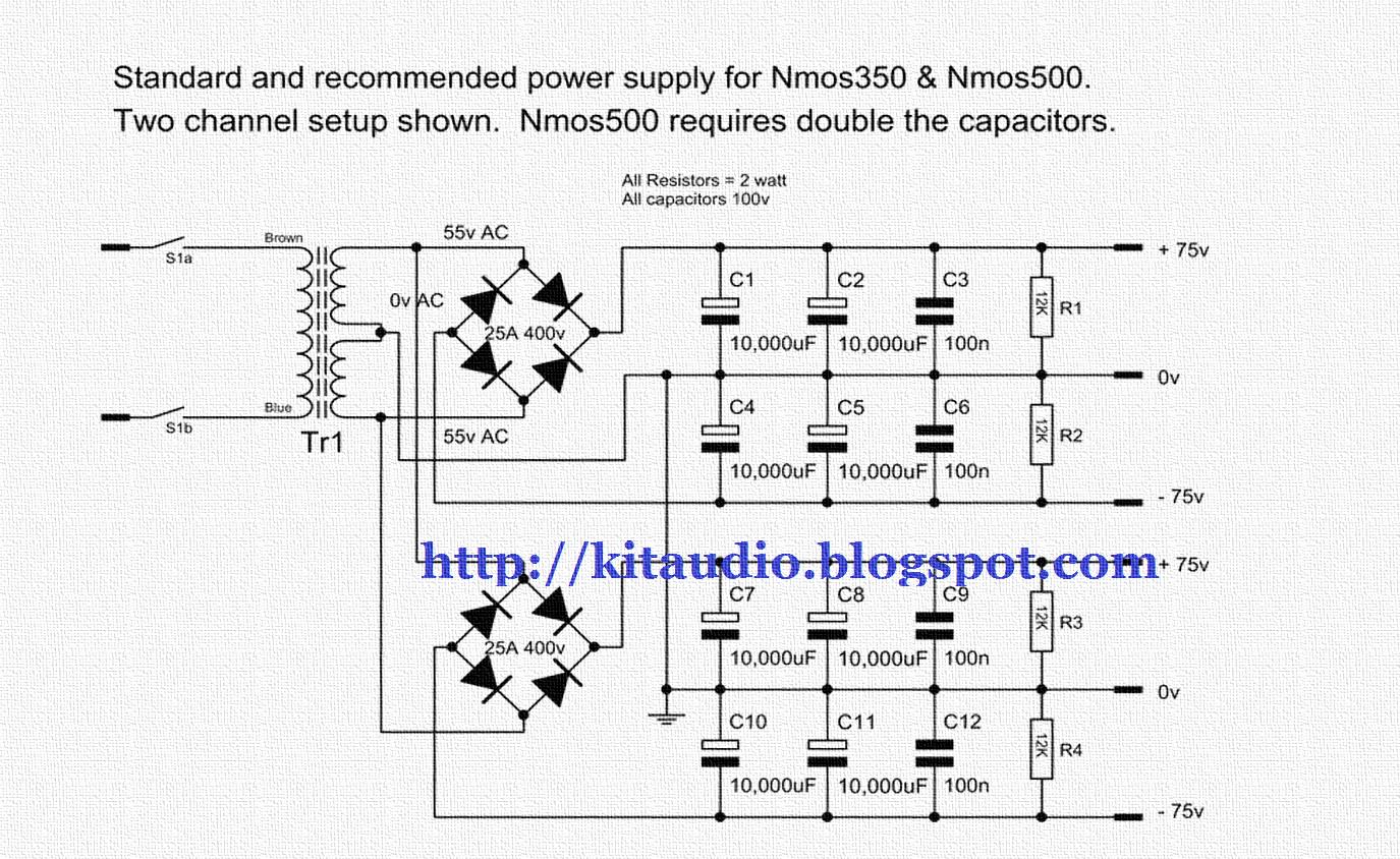
Design considerations for a 5u4g or 274b tube power supply, using a choke. It is for a single channel only.
2N3773 2SC5200 Amplifier Circuit 150W Electronics
To clarify the various concepts, i propose many practical examples using el34, el84, and 12ax7 vacuum tubes, to design the various parts of the circuits and to compute the values of the needed components.
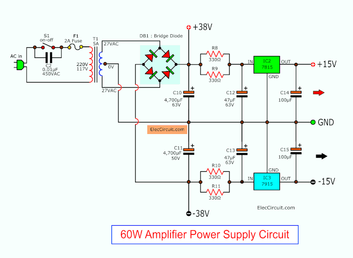
Layout power supply amplifier. 6.4 design of the power supply unit for the vacuum tube amplifier stages the schema of the power supply unit for the stages of the amplifier is given in figure 53. This series represents the world’s most advanced technology in terms of 1 x transformer rated at 1000 watts.
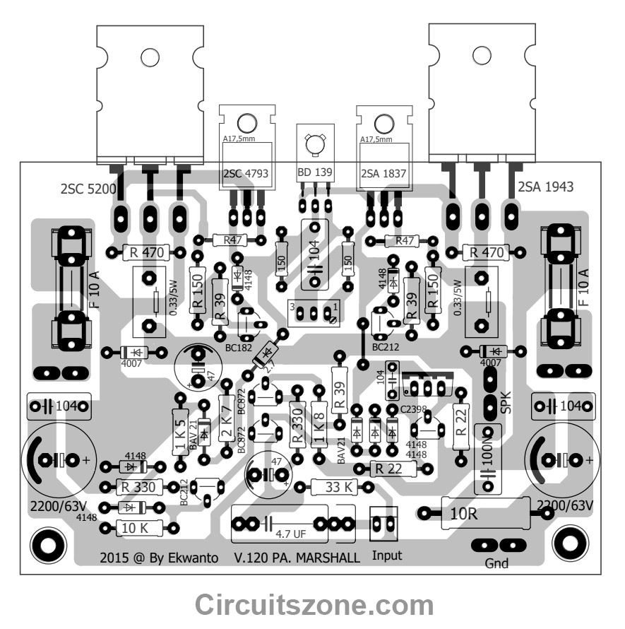
Audio input and input ground wires from the input terminals to the amplifier pcbs; Marshal v 120pa power amplifier pcb layout diy amplifier power amplifiers electronic schematics. Power supply units, as well as exclusive optimized operation management algorithms.
I used 14 awg, but anything larger than 18 awg should be fine. Description many mistakes are made with the power supply, causing the amplifier to hum. 2.0 layout power districts the db210/220 is designed to add additional power to your layout to run more trains by setting up power districts.
As discussed in section 5.1, it is composed of a power supply transformer, a rectifier with its reservoir capacitor, and two sequences of rc smoothing filters, one per each channel. To design a working power amplifier, it is important to configure its output stage correctly. This solution is optimized for sound quality, thermal performance, size, and cost.
• cs1 and cs2 are low value, ceramic capacitors to filter higher frequency noise right at the dc output of the diode bridge. The design of your amplifier pcb layout is critical for good circuit performance, a bad layout will influence the performance because it can introduce leakage resistances, voltage drifts, offset voltages or stray capacitance during your amplifier pb process. A linear regulated power supply;
Gsm 900 mhz, gaas hbt pa design p out = 33 dbm (linear) = 2 w v cc = 3.5v r load = v cc 2 / 2*p out = 3 ω i max = 2*v cc /r load = 2.33 a (note: In this truly diy project, easy to build, the author, vincent thiernesse, proposes a power supply dimensioned for 100 w rms/4 or 8 ω power amplifiers, that behaves like a resistive load with. 120w power amplifier + power supply.
The power supply elements for this amplifier are as given in the following paragraphs. In previous posts in this series i have covered planning the layout of the amplifier, and building and testing a single channel version. Gan systems released the gen2 amplifier and companion power supply reference design today.
Furthermore, the guide also contains a. The modifications associated with this new smart usblite device are mostly to the physical layout and aesthetics of the device hardware only, and do not change the software in any significant way. Step start or inrush limit.
These wires should be thick, as short as possible, and twisted together tightly. Power supply (0.5a), and +5v (5a) external medical grade power supply. Primary windings are supposed to match your house ac supply.
After you complete your physical rf power supply layout, you can use the edb exporter extension to import a design into ansys field solvers and perform a range of si/pi/emi calculations for your design. Expect roughly 10 db per stage 3 stage design The first component of the power supply is the transformer.
The objective of the output stage is primarily to provide current amplification (the voltage gain staying no more than unity) in order that the circuit may supply the high output currents essential for driving a loudspeaker in higher volume level. A power district is an electrically isolated section of the layout including the power wiring, booster and power supply that drives it. 500w power amplifier 2sc2922, 2sa1216 with pcb layout design.
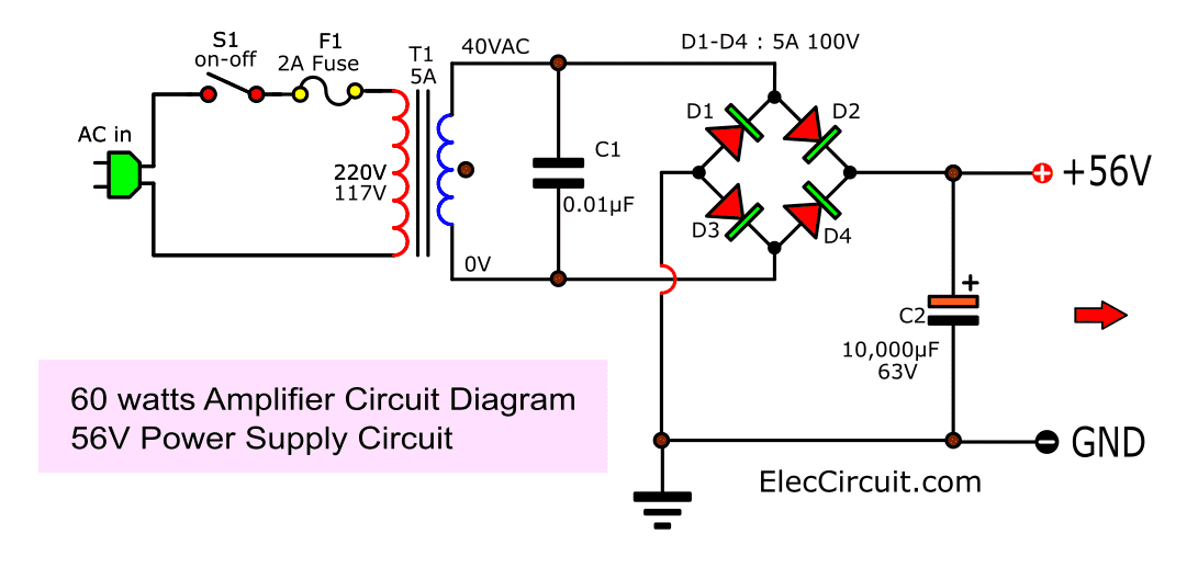
For india and europe the primary winding should be at 240vac rating. This is high power amplifier has output power about 500 watt with the compatible voltage supply is under 63 volt or same. Power amplifier socl506 driver pcb layout in 2020 power amplifiers audio amplifier amplifier.
A simple unregulated power supply consisting of transformer, rectifiers, and reservoir capacitors; • cs3 and cs4 are the large reservoir capacitors to supply large current demands and stabilize the supply rails to minimize low frequency fluctuations. Expect saturated power to be ~ 35 dbm) input power:
Fm amplifier medium power the e series line of indium amplifiers comprises models with an rf power rating of between 2500w and 5000w, usable as a basic module for high power transmitters. Pcb layout class d d2k fb full bridge 2000w diy amplifier power amplifiers class d amplifier Tssl repeater < 2000 laser pump driver optical amplifier pair repeater housing cable to repeater coupling repeater end cover 69cm
This article describes an improved design for a power supply dedicated to audio power amplifiers that exhibits ecological and economical qualities, ideal for audio enthusiasts. When you need the best pcb tools for rf power supply design, look to the complete set of pcb design, layout, and simulation features in altium designer®. Amplifier power supply design power supply inrush protection [ home ] [ up ] let’s work our way left to right through this power supply and see why certain components are used and what characteristics are important in those components.
Once the mistakes are made, it is often impossible to localize them in the power supply, and you'll be looking everywhere at the wrong place, and not find where the hum.
Audio kit Actrk 400 / 600 Watt power amplifier with
layout pcb power amplifier super bass YouTube

100w amplifier circuit with PCB
3kW Power Amplifier Driver Circuit PCB Layout Power

60W RMS OTL integrated audio amplifier circuit
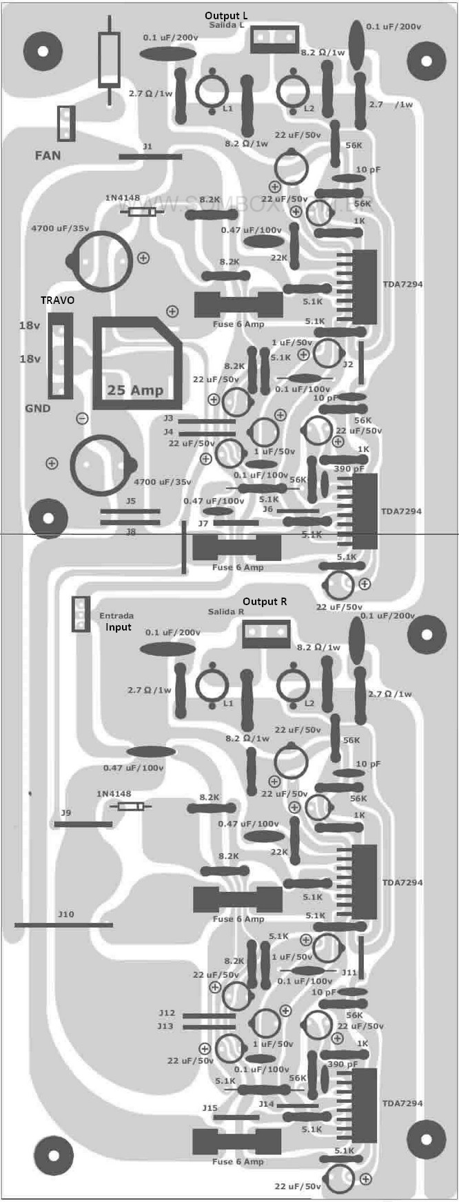
Tda7294 TDA7293 35v 100w subwoofer amplifier circuit

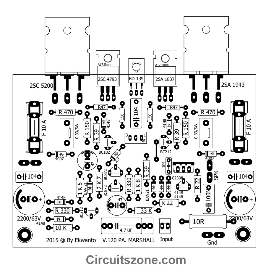
Marshal Power Amplifier HiFi PCB Layout Only
200W Power Amplifier Schematic Diagram & PCB Design

Power Supply for Audio Amplifier circuit,multiple output
Subwoofer Amplifier Circuit Detailed Circuit Diagrams

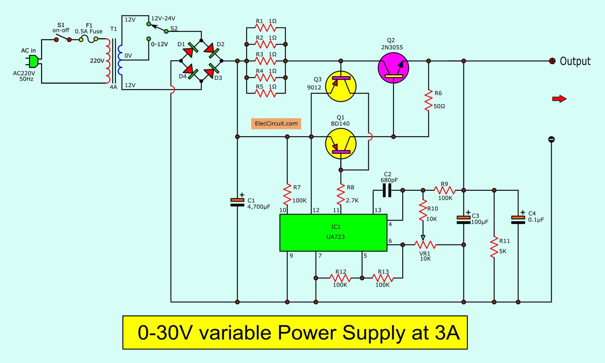
How To Make a Variable Power Supply. 125V & 010A Voltage
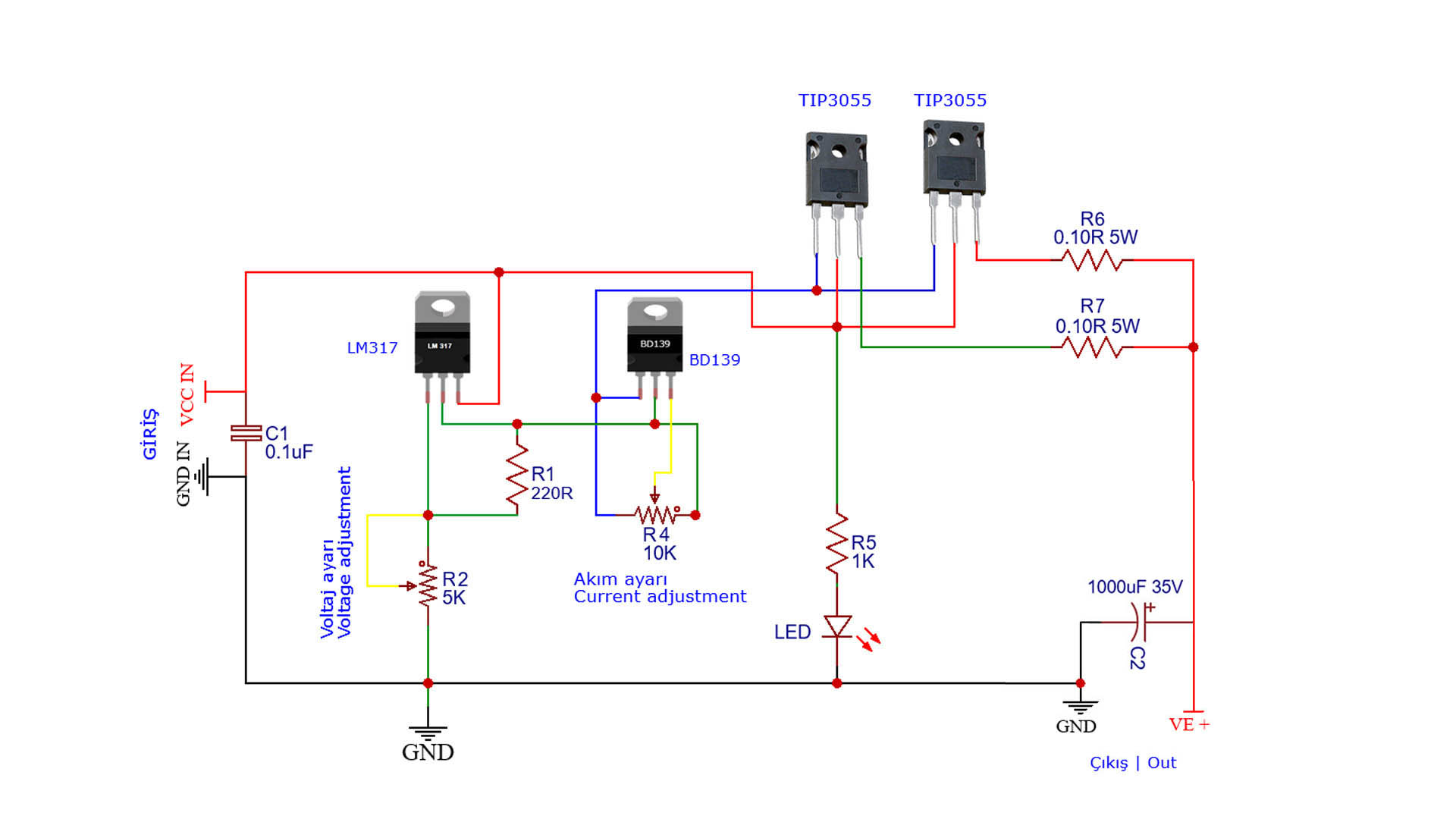
Amplifier Protection and Power Supply Circuits 100w power

030V Variable Power Supply circuit Diagram at 3A
Marshal Power Amplifier HiFi PCB Layout Only
Subwoofer Home Theater Power Amplifier Electronic Circuit

300W RMS Stereo Power Amplifier TDA7294 Schematic, Part
600 Watt Mosfet Power Amplifier Diagram with PCB Gallery

High Voltage Power Supply with Dual Output Power Supply in

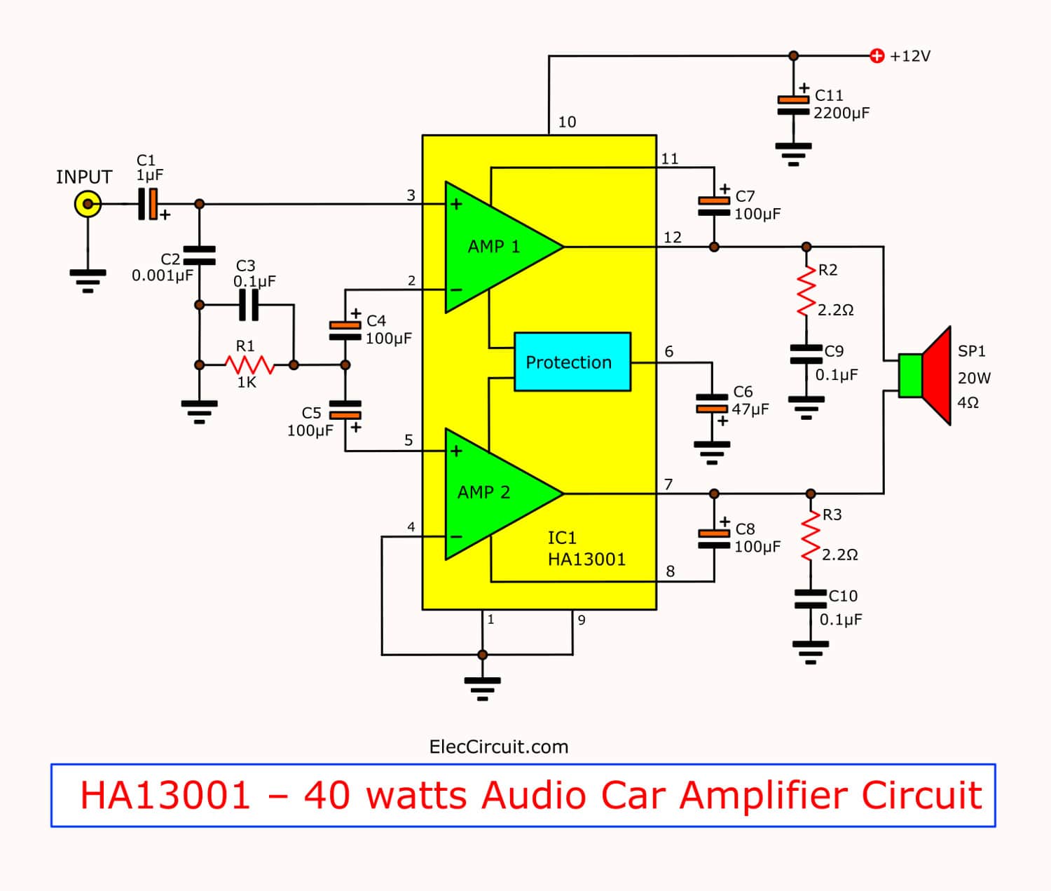
Mini 40 watt audio car amplifier circuit using HA13001