B&g Network Wiring Diagram
All networks are different and require a different wiring. I think that the previous owner disconnected the gps from the system because the rules did not allow networked gauges the last time the boat was raced.
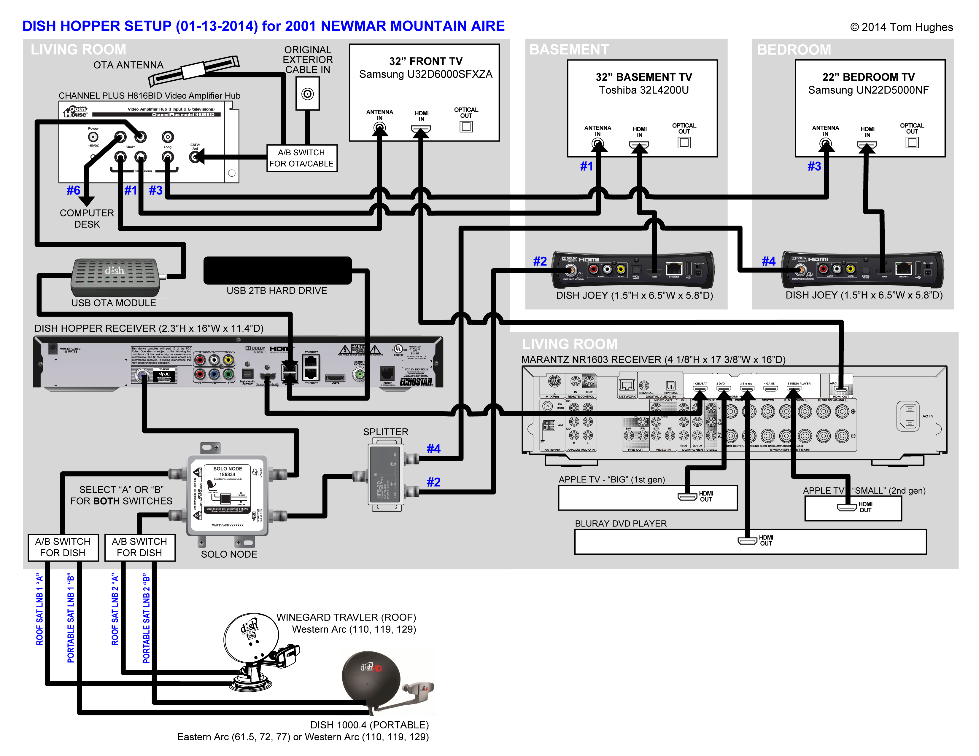
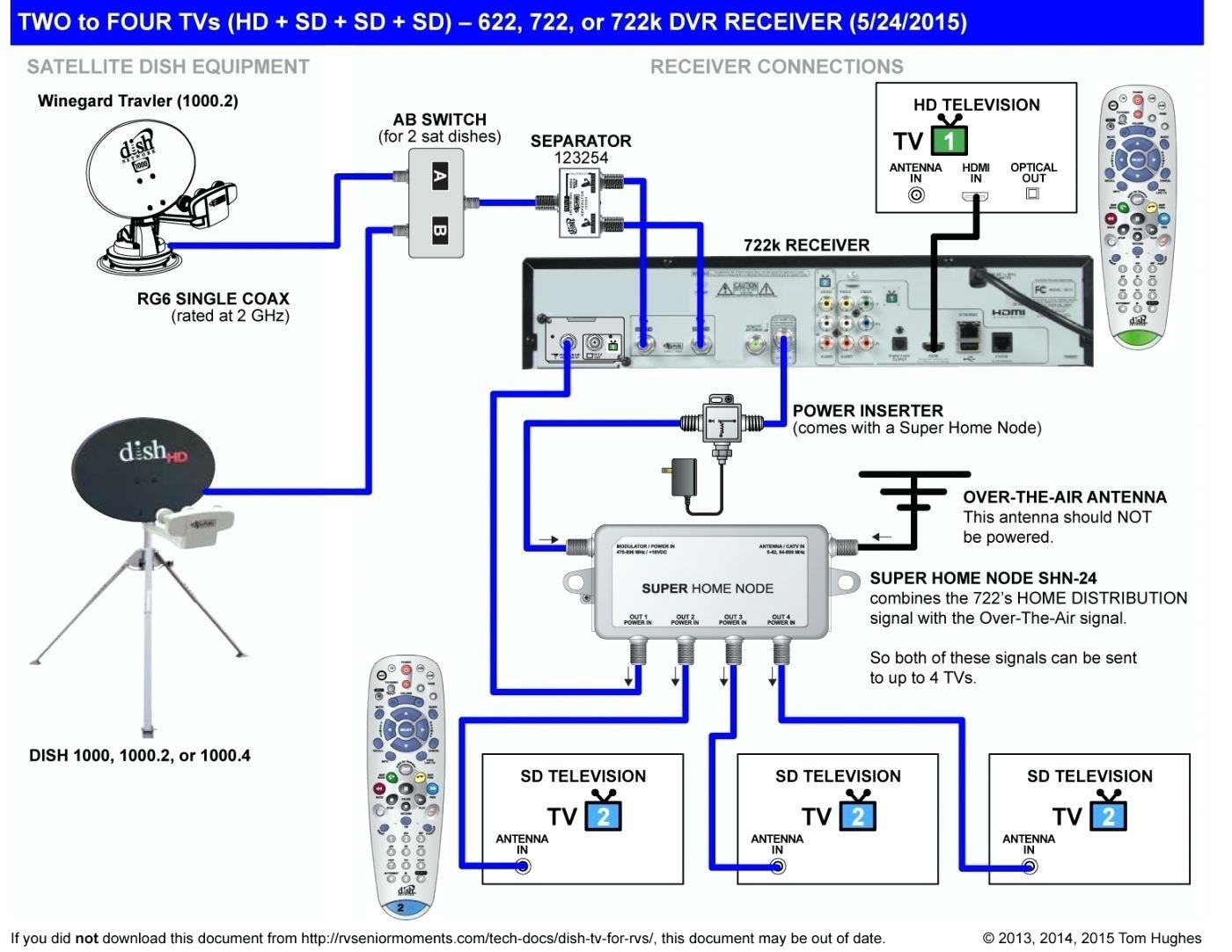
Converting a Winegard Trav’ler Antenna from DirecTV to Dish to Heinzsite Mobile!

As an intelligent system each unit can be used by itself to
B&g network wiring diagram. Of course, my boat's in the water with birw coming next week and i can't haul it and install a newer model in time. It most and matches the complete range of b&g instruments. Note in these ws310 parts and wiring diagrams that the mast cable is not part of the boat’s nmea 2000 network.
Below is a wiring diagram for the hydra 2000 range, but other b&g ranges will be slightly different. Network pilot installation manual (acp) download : The ws320 wireless wind sensor pack offers a high performance solution, with exceptional data accuracy and improved aerodynamics, which is easy to install and includes all the parts you need.
Stands for ‘parameter group number’. This world beating series of intelligent navigational instruments has been brought to you through a combination of scientific innovation and high quality production to create a computerised data system you can trust. This example was created in conceptdraw diagram using the computer and networks solution from the computer and networks area of conceptdraw solution park and.
Why did b&g go to such trouble? 7 about b&g 7 about this manual 8 system introduction 9 h5000 system example 10 h5000 performance system example 11 h5000 typical autopilot system 12 planning 12 mounting locations 14 system architecture 14 nmea 2000® device connection 15 wiring guidelines 16 network layout 17 bridged network 18 network power supply 19 h5000 central processor. Network vhf 2 up receiver channels 84 frequency range 156.050 to 163.275 mhz sensitivity 0.25 uv at 12 db sinad.
The simnet backbone must be kept intact when a product is removed from the network. The diagram below illustrates how an nmea 2000 network is put together: A single network cable is used to carry data and power between units.
Using terminal wiring for terminal wiring, use 18 awg to 22 awg (1.02 mm to 0.65 mm) wire. You can use either of the configurations for your network cables, so long as you use the same one on both ends of the cat6 wire. They can be simple and consist of two computers connected with a network cable, or complex and consist of several computers, switches, hubs.
See wiring diagram (figure 3). H5000 fastnet interface the h5000 fastnet interface provides a b&g supported solution for customers wishing to progressively upgrade h3000 systems and/or replace displays on an h3000 system with the latest h5000 graphic displays If sdix is configured for sdi2, use either sdi2 bus.
This network consists of two legs, one leg extending in each direction from the power insertion point. Instead, there’s a short network interface cable that presumably converts an analog signal coming down the mast into n2k wind pgns (messages) while also sending a little n2k 12v power up to the sensor. B&g instruments have been produced for many years and there are too many different ranges and models to cover every possible system in this post.
The thing works except the gps and speed. Genetic interaction networks highlight mechanistic connections between. Daisy chain daisy chaining is a simple method of interconnecting products mounted adjacent to each other in a panel.
The b&g network range of instruments is designed for use as individual units or connected together to form an integrated navigational system. You will need a handful of tools and components to complete this process. 1.4 network backbone note !
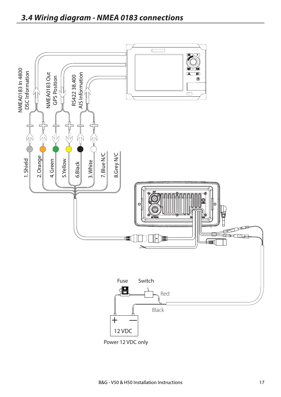
Most b&g systems since the 1980s will have an nmea0183 output somewhere in the instrument network. The global network illustrates how coherent sets of genetic interactions connect protein complex and pathway modules to map a functional wiring diagram of the cell. Hi, i have a b&g network quad system that came on my boat.
I found the attached wiring diagram of the b&g equipment, unfortunately it does not show the cbridge that seems to be installed on ventus and it only explains 3 of 5 network cables going into the hub which were the ones i could already explain. So, i'm desperately looking for a new or used, but functioning, replacement and have had zero luck. From my poor reading of the hanse circuit diagram of the boat, i *think* there is a 15 amp fuse on the ap circuit.
Wiring diagram book a1 15 b1 b2 16 18 b3 a2 b1 b3 15 supply voltage 16 18 l m h 2 levels b2 l1 f u 1 460 v f u 2 l2 l3 gnd h1 h3 h2 h4 f u 3 x1a f u 4 f u 5 x2a r power on optional x1 x2115 v 230 v h1 h3 h2 h4 optional connection electrostatically shielded transformer f u 6 off on m l1 l2 1 2 stop ol m start 3 start start fiber optic. Welcome to the b&g network system. The messages used by nmea 2000 devices for sharing information.
You have been successfully registered. The latest technology and screened cables throughout the network system ensure the 3.7 maximum power supply voltage drop the nmea 2000® network is designed to work properly
The length of cable that connects an nmea 20000 device to the backbone pgn: Wiring diagram wiring dtagram controls and connectors 1. Vessels and is any network where the power is connected to the network at some location other than at the end.
Control panel to module wiring overview in the following sections, this document provides instructions for wiring devices to your control panel. We have sent a verification link to to complete your registration. View and download b&g network pilot (acp) instruction manual online.
Ws320 wireless wind pack with interface. A wireless wind sensor from b&g, designed for cruising and club racing sailors. You can use interconnect or terminal wiring.
I have a wind, speed/depth, gps and compass.
B&G H5000 Introduction

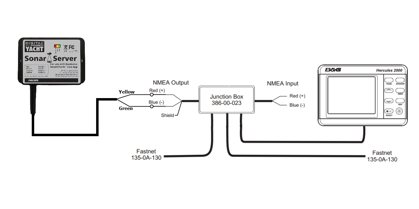
Interfacing to B&G Instruments Sonar Server
Dish Network Dph42 Wiring Diagram
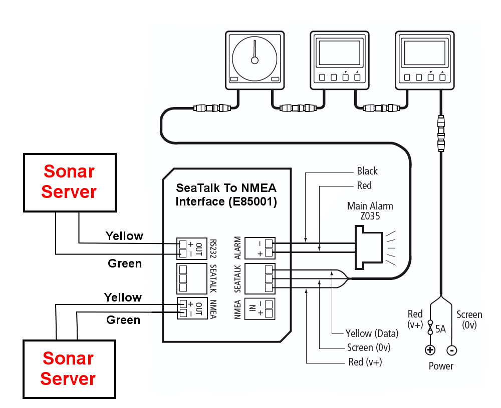
Interfacing to old Autohelm/Raymarine SeaTalk Systems Sonar Server German
CKD Boats Roy Mc Bride B&G Network MHU 496 wire and pin changes

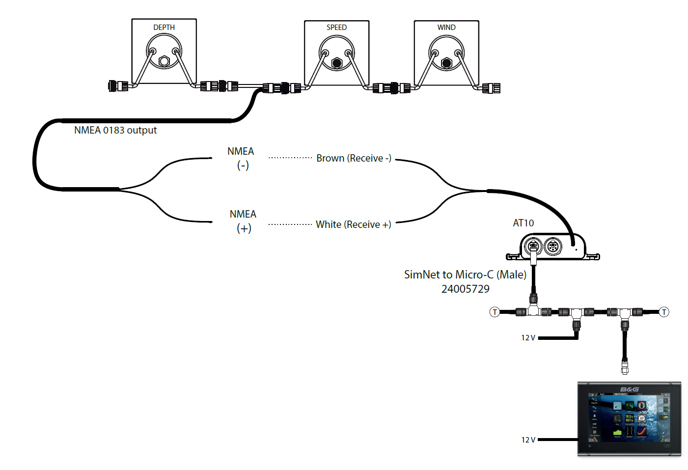
How to add a Vulcan chartplotter to any boat B&G
Pin on DIY and crafts

GPS545 to NMEA2000? The Hull Truth Boating and Fishing Forum

Dish Network Dph42 Wiring Diagram

CKD Boats Roy Mc Bride B&G Network fluxgate compass wiring

CKD Boats Roy Mc Bride B&G Network fluxgate compass wiring

4 wiring diagram nmea 0183 connections B&G H50 Wireless VHF Handset User Manual Page 17 / 22
Interfacing to old Autohelm/Raymarine SeaTalk Systems Sonar Server

Dish 722 Wiring Diagram Wiring Diagram Blog Dish Vip722K Wiring Diagram Cadician's Blog
NMEA2000 network s/v Jedi
Rj11 Wiring Diagram Cadician's Blog
Marine Networking Guide
iSailor Digital Yacht News

Dpp44 Wiring Diagram
